
| MAKE | MODEL | YEAR RANGE | SPECIFIC DETAILS |
|---|---|---|---|
| TOYOTA | AVALON | 2005 – 2012 | All Models |
| TOYOTA | CAMRY | 2002 – 2006 | SE or XLE Model |
| TOYOTA | CAMRY | 2004 | LE Model w/ 16″ Wheels |
| TOYOTA | CAMRY | 2007 – 2011 | Except Hybrid Model |
| TOYOTA | SOLARA | 2004 – 2008 | All Models |
| LEXUS | ES300 | 2002 – 2003 | All Models |
| LEXUS | ES330 | 2004 – 2006 | All Models |
| LEXUS | ES350 | 2007 – 2012 | All Models |
Components
POWER STEERING: POWER STEERING LINK:
COMPONENTS
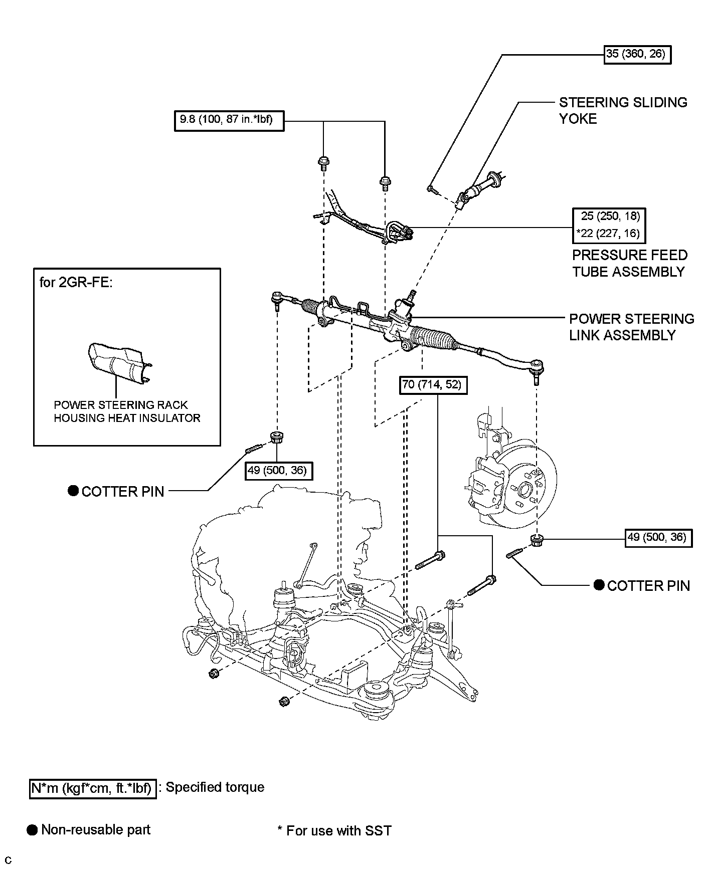
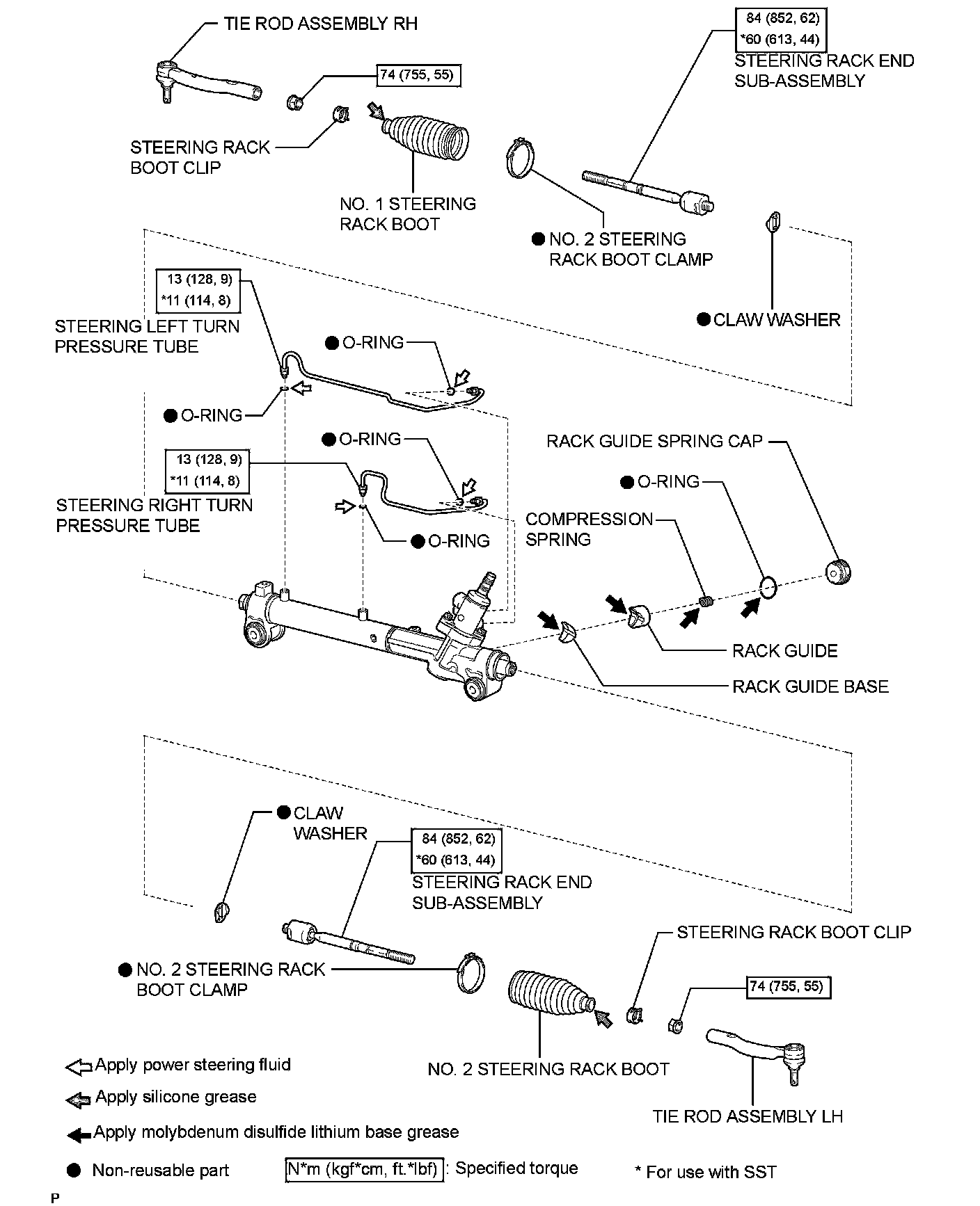
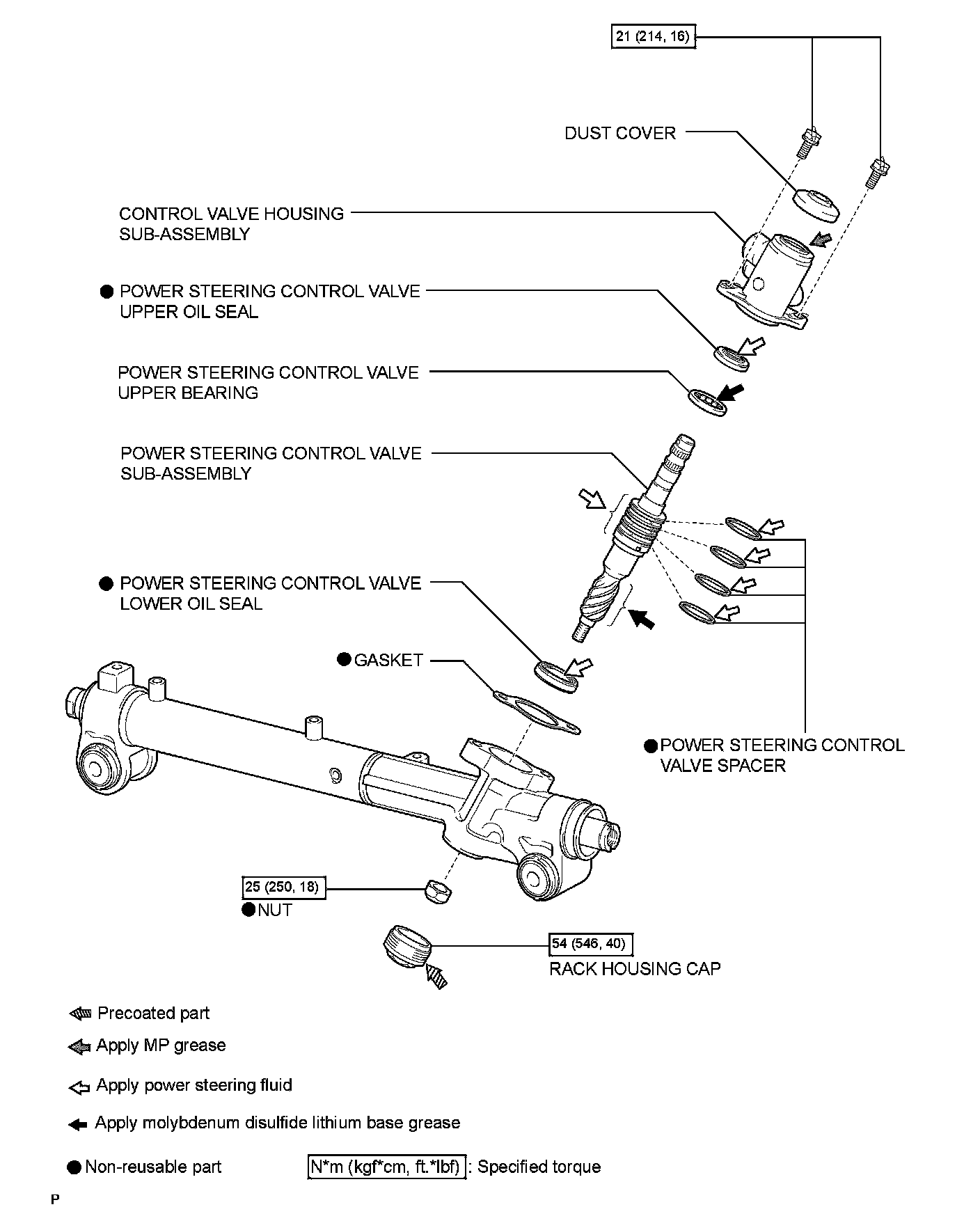
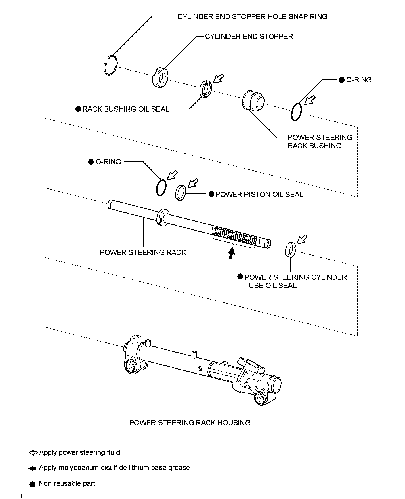
Removal
REMOVAL
1. PLACE FRONT WHEELS FACING STRAIGHT AHEAD
2. DISCONNECT CABLE FROM NEGATIVE BATTERY TERMINAL
3. REMOVE FRONT WHEELS
4. SEPARATE STEERING SLIDING YOKE
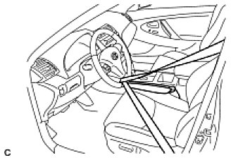
(a) Secure the steering wheel with the seat belt in order to prevent rotation.
HINT: This operation is useful to prevent damage to the spiral cable.
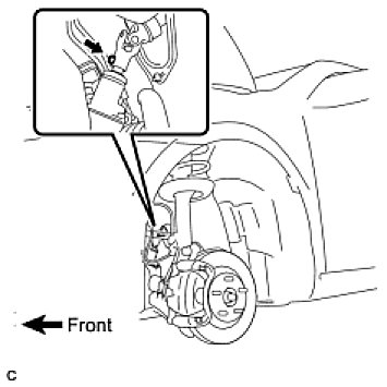
(b) Remove the bolt and slide the steering sliding yoke.
NOTE: Do not separate the steering sliding yoke from the power steering link assembly.
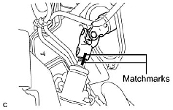
(c) Put matchmarks on the steering sliding yoke and the power steering link assembly.
(d) Separate the steering sliding yoke from the power steering link assembly.
5. SEPARATE TIE ROD ASSEMBLY LH
(a) Remove the cotter pin and the nut.
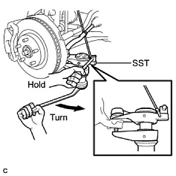
(b) Using SST, separate the tie rod assembly LH from the steering knuckle.
SST: 09628-00011
– Hang SST with a string, etc. to prevent it from falling.
– Do not damage the front disc brake dust cover.
– Do not damage the ball jointdust cover.
– Do not damage the steering knuckle.
6. SEPARATE TIE ROD ASSEMBLY RH
HINT: Perform the same procedure as for the LH side.
7. REMOVE ENGINE ASSEMBLY WITH TRANSAXLE
HINT: Refer to the instructions for removal of the engine assembly (Removal) for 2AZ-FE, (Removal) for 2GR-FE).
8. DISCONNECT PRESSURE FEED TUBE ASSEMBLY
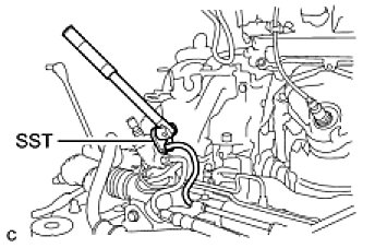
(a) Using SST, disconnect the pressure feed tube assembly (return tube side) from the power steering link assembly.
SST: 09023-12701
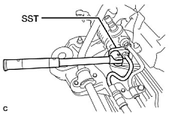
(b) Using SST, disconnect the pressure feed tube assembly (pressure feed tube side) from the power steering link assembly.
SST: 09023-12701
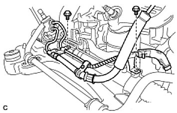
(c) Remove the 2 bolts and separate the pressure feed tube clamp.
9. REMOVE POWER STEERING LINK ASSEMBLY
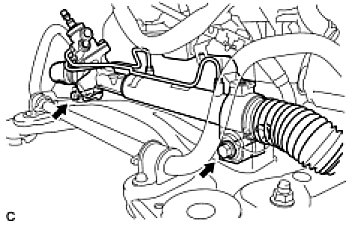
(a) Remove the 2 bolts, 2 nuts, and the power steering link assembly.
NOTE: Because the nut has its own stopper, do not turn the nut. Loosen the bolt with the nut fixed.
10. REMOVE POWER STEERING RACK HOUSING HEAT INSULATOR (for 2GR-FE)
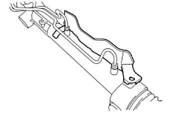
(a) Remove the power steering rack housing heat insulator from the power steering link assembly.
Disassembly
DISASSEMBLY
1. SECURE POWER STEERING LINK ASSEMBLY
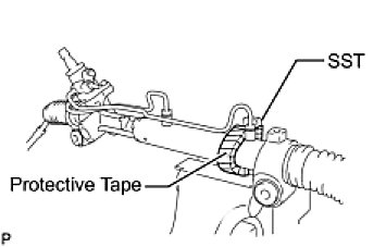
(a) Using SST, secure the power steering link assembly.
SST: 09612-00012
HINT: Tape the SST before use.
2. REMOVE STEERING LEFT TURN PRESSURE TUBE
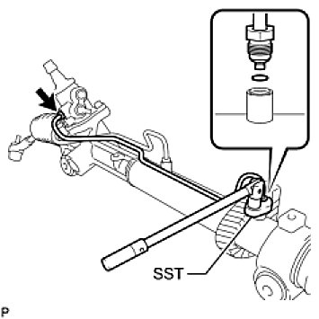
(a) Using SST, remove the steering left turn pressure tube.
SST: 09023-38201
(b) Remove the 2 O-rings from the steering left turn pressure tube.
3. REMOVE STEERING RIGHT TURN PRESSURE TUBE
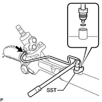
(a) Using SST, remove the steering right turn pressure tube.
SST: 09023-38201
(b) Remove the 2 O-rings from the steering right turn pressure tube.
4. REMOVE TIE ROD ASSEMBLY LH
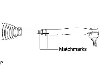
(a) Put matchmarks on the tie rod assembly LH and the steering rack end sub-assembly.
(b) Loosen the lock nut, and remove the tie rod assembly LH and the lock nut.
5. REMOVE TIE ROD ASSEMBLY RH
HINT: Perform the same procedure as for the LH side.
6. REMOVE STEERING RACK BOOT CLIP
(a) Using pliers, remove the 2 steering rack boot clips.
7. REMOVE NO. 2 STEERING RACK BOOT CLAMP
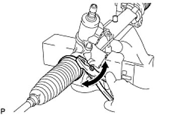
(a) Using pliers, remove the 2 No. 2 steering rack boot clamps as shown in the illustration.
NOTE: Be careful not to damage the No. 2 steering rack boot.
8. REMOVE NO. 2 STEERING RACK BOOT
(a) Remove the No. 2 steering rack boot.
9. REMOVE NO. 1 STEERING RACK BOOT
(a) Remove the No. 1 steering rack boot.
10. REMOVE STEERING RACK END SUB-ASSEMBLY
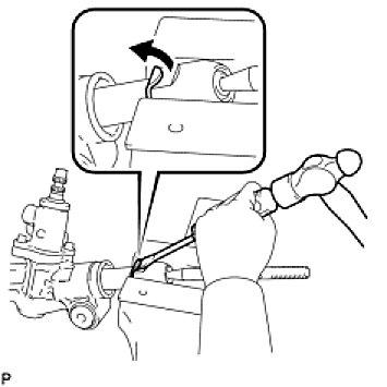
(a) Using a screwdriver and a hammer, unstake the RH and LH claw washers.
NOTE: Avoid any impact to the steering rack.
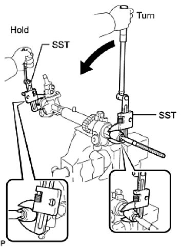
(b) Using SST, remove the steering rack end sub-assembly (RH side) and the claw washer.
SST: 09922-10010
NOTE: Use SST 09922-10010 as shown in the illustration.
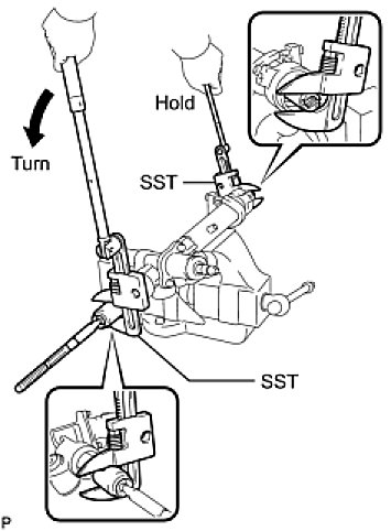
(c) Using SST, remove the steering rack end sub-assembly (LH side) and the claw washer.
SST: 09922-10010
NOTE: Use SST 09922-10010 as shown in the illustration.
HINT: Using SST, hold the rack and remove the steering rack end sub-assembly.
11. REMOVE RACK GUIDE
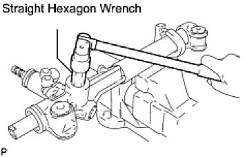
(a) Using a straight hexagon wrench (24 mm (0.94 in.)), remove the rack guide spring cap.
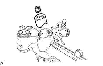
(b) Remove the compression spring and the rack guide sub-assembly.
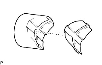
(c) Remove the rack guide base from the rack guide.
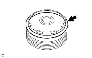
(d) Remove the O-ring from the rack guide spring cap.
12. REMOVE DUST COVER
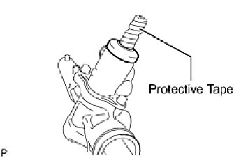
(a) Wrap protective tape around the spline of the control valve in order to prevent damaging the dust cover.
(b) Remove the dust cover.
13. REMOVE POWER STEERING CONTROL VALVE ASSEMBLY
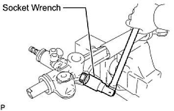
(a) Using a socket wrench (27 mm (1.06 in.)), remove the rack housing cap.
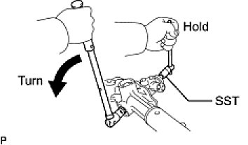
(b) Using SST, hold the control valve shaft and remove the nut.
SST: 09616-00011
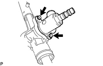
(c) Remove the 2 bolts and the power steering control valve assembly.
(d) Remove the gasket.
14. REMOVE POWER STEERING CONTROL VALVE SUB-ASSEMBLY
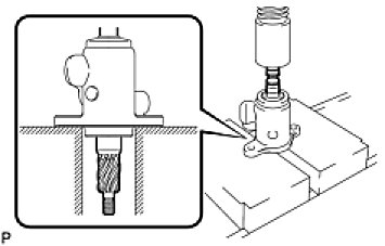
(a) Using a press, remove the power steering control valve sub-assembly.
15. REMOVE POWER STEERING CONTROL VALVE LOWER OIL SEAL
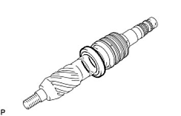
(a) Remove the power steering control valve lower oil seal from the power steering control valve sub-assembly.
16. REMOVE POWER STEERING CONTROL VALVE SPACER
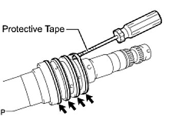
(a) Using a screwdriver, remove the 4 power steering control valve spacers from the power steering control valve sub-assembly.
NOTE: Be careful not to damage the spacer grooves on the control valve.
HINT: Tape the screwdriver tip before use.
17. REMOVE POWER STEERING CONTROL VALVE UPPER OIL SEAL
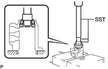
(a) Using SST and a press, press out the power steering control valve upper oil seal and the power steering control valve upper bearing from the control valve housing sub-assembly.
SST: 09950-70010
09951-07150
SST: 09950-60010
09951-00250
09951-00180
09952-06010
18. REMOVE CYLINDER END STOPPER HOLE SNAP RING
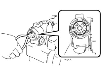
(a) Using needle-nose pliers, remove the cylinder end stopper hole snap ring from the power steering rack housing.
19. REMOVE POWER STEERING RACK SUB-ASSEMBLY
(a) Remove the power steering rack sub-assembly with the cylinder end stopper and power steering rack bushing.
20. REMOVE CYLINDER END STOPPER
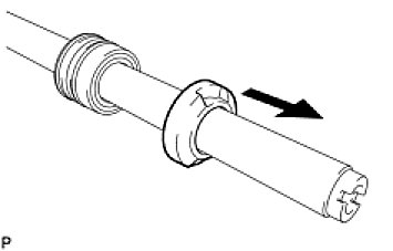
(a) Remove the cylinder end stopper from the power steering rack sub-assembly.
21. REMOVE POWER STEERING RACK BUSHING
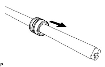
(a) Remove the power steering rack bushing from the power steering rack sub-assembly.
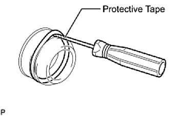
(b) Using a screwdriver, remove the O-ring from the power steering rack bushing.
HINT: Tape the screwdriver tip before use.
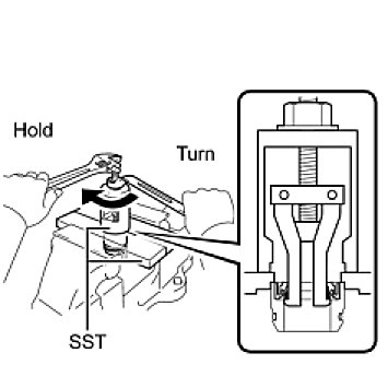
(c) Using SST, remove the rack bushing oil seal from the power steering rack bushing.
SST: 09527-21011
SST: 09612-24014
09613-22011
NOTE: Be careful not to drop the power steering rack bushing.
22. REMOVE POWER STEERING CYLINDER TUBE OIL SEAL
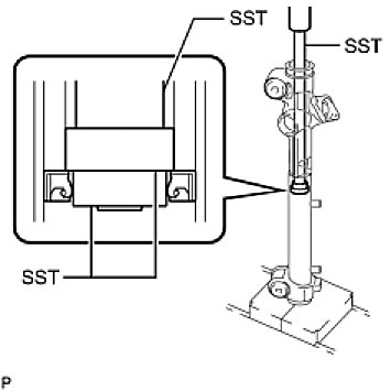
(a) Using SST and a press, remove the power steering cylinder tube oil seal.
SST: 09950-70010
09951-07360
SST: 09950-60010
09951-00290
09951-00250
NOTE: Be careful not to damage the inside surface of the power steering rack housing.
23. REMOVE POWER PISTON OIL SEAL
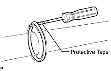
(a) Using a screwdriver, remove the power piston oil seal and the O-ring from the power steering rack.
NOTE: Be careful not to damage the power piston oil seal groove on the power steering rack.
HINT: Tape the screwdriver tip before use.
Reassembly
NOTE: When installing parts, coat the parts indicated by arrows with power steering fluid, molybdenum disulfide lithium base grease, MP grease or silicon grease (Components).
1. INSTALL POWER PISTON OIL SEAL
(a) Coat a new O-ring with power steering fluid and install it to the steering rack.
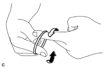
(b) Expand a new power piston oil seal with your fingers.
NOTE: Be careful not to expand the oil seal excessively.
(c) Coat the power piston oil seal with power steering fluid.
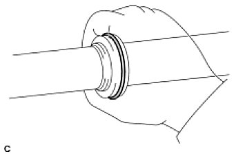
(d) Install the power piston oil seal to the steering rack, and adjust it with your fingers.
2. INSTALL POWER STEERING CYLINDER TUBE OIL SEAL
(a) Apply power steering fluid to the lip of a new power steering cylinder tube oil seal.
(b) Install the power steering cylinder tube oil seal to the rack housing at a slant.
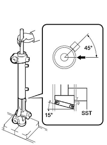
(c) Using SST, insert the power steering cylinder tube oil seal by pushing the SST in by hand until the oil seal passes the 2 ports.
SST: 09950-70010
09951-07360
SST: 09631-00200
– Ensure that the power steering cylinder tube oil seal is installed in the correct direction as shown in the illustration.
– Install the power steering cylinder tube oil seal at an angle of approximately 15° so that the lowermost part comes to the point, indicated by the arrow in the illustration, to prevent damage to the side of the oil seal when it passes the 2 ports.
– Do not turn the SST when inserting the oil seal.
(d) Install SST (09631-00200) to SST (09951-07360) upside down.
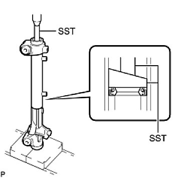
(e) Using SST, level the power steering cylinder tube oil seal by pushing the SST in by hand. Using SST and a press, install the oil seal.
SST: 09950-70010
09951-07360
SST: 09631-00200
3. INSTALL POWER STEERING RACK SUB-ASSEMBLY
(a) Apply molybdenum disulfide lithium base grease to the rack teeth ends.
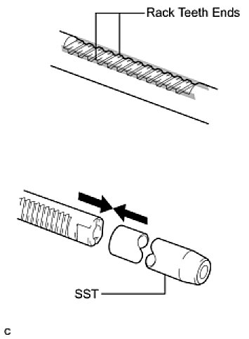
(b) Connect SST to the power steering rack sub-assembly.
SST: 09631-33010
(c) Coat SST with power steering fluid.
(d) Install the power steering rack sub-assembly to the power steering rack housing.
(e) Remove SST.
4. INSTALL POWER STEERING RACK BUSHING
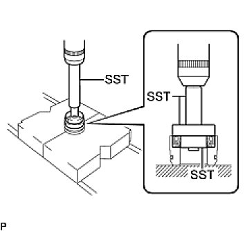
(a) Using SST and a press, install the rack bushing oil seal to the power steering rack bushing.
SST: 09950-70010
09951-07100
SST: 09950-60010
09951-00400
09951-00250
09952-06010
NOTE: Ensure that the rack bushing oil seal is installed in the correct direction as shown in the illustration.
(b) Coat a new O-ring with power steering fluid and install it to the rack bushing.
(c) Coat the rack bushing oil seal lip with power steering fluid.
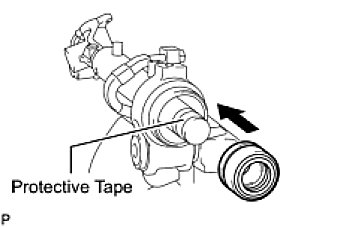
(d) Install the power steering rack bushing to the power steering rack housing.
NOTE: Do not damage the rack bushing oil seal.
HINT: Wrap protective tape around the end of the steering rack in order to prevent damage to the rack bushing oil seal.
5. INSTALL CYLINDER END STOPPER
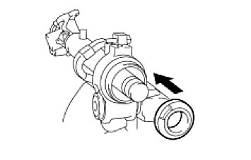
(a) Install the cylinder end stopper to the power steering rack housing.
6. INSTALL CYLINDER END STOPPER HOLE SNAP RING
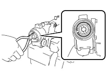
(a) Using needle nose pliers, install the cylinder end stopper hole snap ring to the power steering rack housing.
– Make sure that the cylinder end stopper hole snap ring is securely installed in the power steering rack housing groove.
– Make sure that the cylinder end stopper hole snap ring claws are aligned with the cylinder end stopper notch.
7. AIR TIGHTNESS TEST
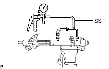
(a) Install SST to the power steering rack housing.
SST: 09631-12071
09633-00010
(b) Apply a vacuum of 53 kPa (398 mmHg, 15.65 in.Hg) for approximately 30 seconds.
(c) Check that there is no change in the vacuum pressure.
If there is a change in the vacuum pressure, check the installation of the oil seals.
8. INSTALL POWER STEERING CONTROL VALVE UPPER OIL SEAL
(a) Coat a new power steering control valve upper oil seal lip with power steering fluid.
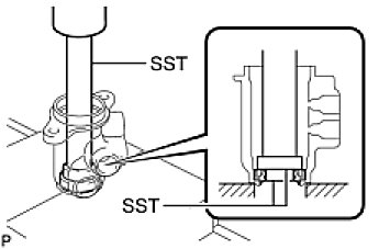
(b) Using SST and a press, press in the power steering control valve upper oil seal.
SST: 09950-70010
09951-07150
SST: 09950-60010
09951-00180
09952-06010
09951-00320
NOTE: Make sure that the power steering control valve upper oil seal is installed in the correct direction as shown in the illustration.
9. INSTALL POWER STEERING CONTROL VALVE UPPER BEARING
(a) Coat the power steering control valve upper bearing with molybdenum disulfide lithium base grease.
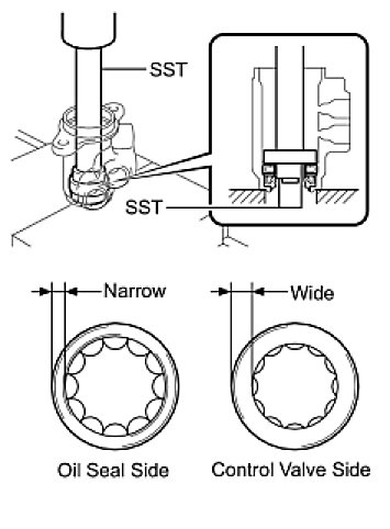
(b) Using SST and a press, press in the power steering control valve upper bearing.
SST: 09950-70010
09951-07150
SST: 09950-60010
09951-00180
09951-00340
NOTE: Make sure that the power steering control valve upper bearing is installed in the correct direction as shown in the illustration.
10. INSTALL POWER STEERING CONTROL VALVE SPACER
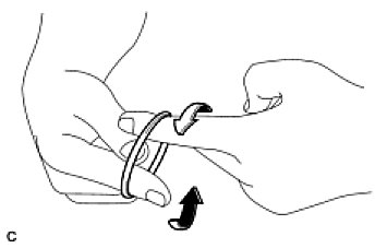
(a) Expand 4 new power steering control valve spacers with your fingers.
NOTE: Be careful not to expand the power steering control valve spacers excessively.
(b) Coat the 4 power steering control valve spacers with power steering fluid.
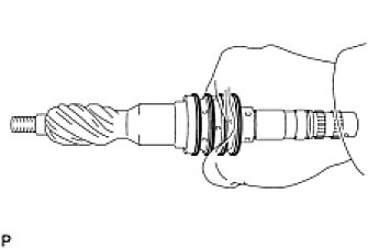
(c) Install the 4 power steering control valve spacers to the control valve, and adjust them with your fingers.
11. INSTALL POWER STEERING CONTROL VALVE SUB-ASSEMBLY
(a) Coat the power steering control valve sub-assembly with power steering fluid.
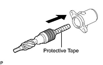
(b) Install the power steering control valve sub-assembly into the control valve housing sub-assembly.
NOTE: Be careful not to damage the power steering control valve spacers and power steering control valve upper oil seal lip.
HINT: Wrap protective tape around the spline of the power steering control valve sub-assembly in order to prevent damage to the oil seal.
12. INSTALL POWER STEERING CONTROL VALVE LOWER OIL SEAL
(a) Coat a new power steering control valve lower oil seal lip with power steering fluid.
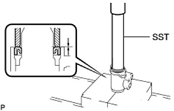
(b) Using SST and a press, install the power steering control valve lower oil seal to the control valve assembly.
SST: 09612-22011
– Make sure that the power steering control valve lower oil seal is installed in the correct direction as shown in the illustration.
– Do not damage the power steering control valve lower oil seal.
13. INSTALL POWER STEERING CONTROL VALVE ASSEMBLY
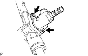
(a) Install the power steering control valve assembly and a new gasket to the power steering rack housing with the 2 bolts.
Torque: 21 Nm (214 kgf-cm, 16 ft-lbf)
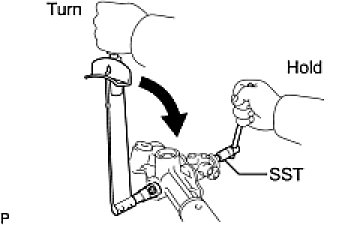
(b) Using SST, hold the control valve shaft and install a new nut.
SST: 09616-00011
Torque: 25 Nm (250 kgf-cm, 18 ft-lbf)
(c) Apply sealant to 2 or 3 threads of the rack housing cap.
Sealant:
TOYOTA genuine adhesive 1344, THREE BOND 1344 or equivalent
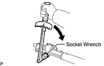
(d) Using a socket wrench (27 mm (1.06 in.)), install the rack housing cap.
Torque: 54 Nm (546 kgf-cm, 40 ft-lbf)
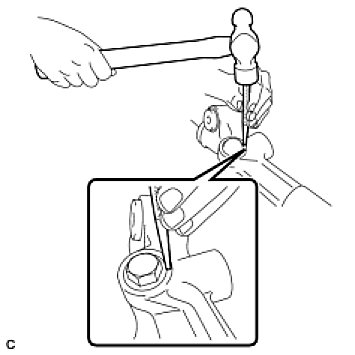
(e) Using a punch and a hammer, stake the rack housing cap and the power steering rack housing.
14. INSTALL RACK GUIDE
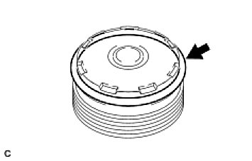
(a) Coat a new O-ring with molybdenum disulfide lithium base grease and install it to the rack guide spring cap.
NOTE: Make sure that no foreign matter, such as aluminum dust, is on the power steering rack housing and rack guide spring cap.
(b) Apply molybdenum disulfide lithium base grease to the rack guide base and rack guide.
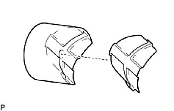
(c) Install the rack guide base to the rack guide.
(d) Apply molybdenum disulfide lithium base grease to the compression spring and the contact surface of the rack guide sub-assembly and the power steering rack.
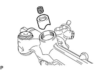
(e) Install the compression spring and rack guide sub-assembly to the power steering rack housing.
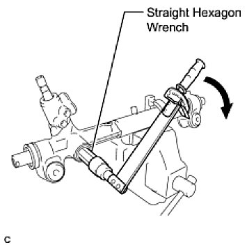
(f) Using a straight hexagon wrench (24 mm (0.94 in.)), install the rack guide spring cap to the power steering rack housing.
Torque: 50 to 70 Nm (514 to 714 kgf-cm, 37 to 52 ft-lbf)
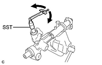
(g) Using SST, turn the control valve and measure the turning torque.
Torque: 6.0 Nm (61 kgf-cm, 54 in-lbf)
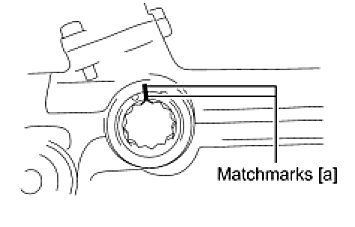
(h) Put matchmarks [a] on the power steering rack housing and the rack guide spring cap.
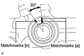
(i) Put matchmarks [b] 30° counterclockwise from matchmarks [a] on the power steering rack housing.
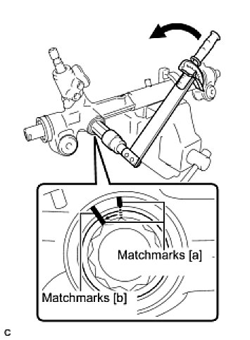
(j) Using a straight hexagon wrench (24 mm (0.94 in.)), loosen the rack guide spring cap until matchmarks [b] and matchmarks [a] on the rack guide spring cap are aligned. Measure the rotating torque required when loosening the rack guide spring cap.
Torque: 10 Nm (102 kgf-cm, 7.4 ft-lbf)
(k) If the rotating torque required when loosening is below the specified value, perform the following procedure to achieve the specified value.
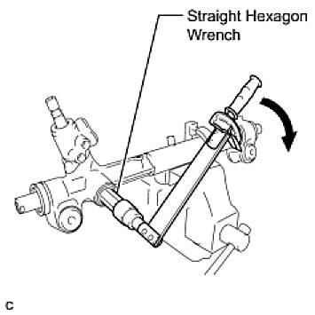
(1) Using a straight hexagon wrench (24 mm (0.94 in.)), re-tighten the rack guide spring cap.
Torque: 50 to 70 Nm (510 to 714 kgf-cm, 37 to 52 ft-lbf)
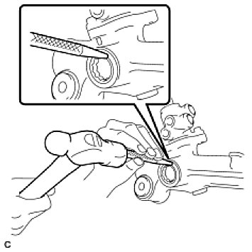
(2) Using a punch and hammer, stake the power steering rack housing and rack guide spring cap at 3 equally spaced positions.
HINT: Tap the power steering rack housing and rack guide spring cap strongly and repeatedly to stake them securely.
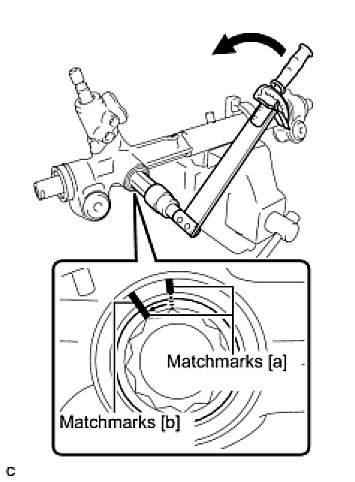
(3) Using a straight hexagon wrench (24 mm (0.94 in.)), loosen the rack guide spring cap until matchmarks [b] and matchmarks [a] on the rack guide spring cap are aligned. Measure the rotating torque required when loosening the rack guide spring cap.
Torque: 10 Nm (102 kgf-cm, 7.4 ft-lbf)
15. INSPECT TOTAL PRELOAD (Testing and Inspection)
16. INSTALL DUST COVER
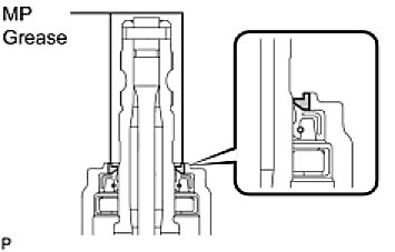
(a) Apply MP grease around the control valve shaft as shown in the illustration.
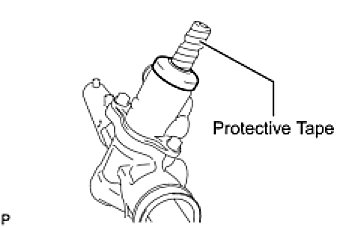
(b) Wrap vinyl tape around the spline of the control valve.
(c) Install the dust cover to the control valve assembly.
17. INSTALL STEERING RACK END SUB-ASSEMBLY
(a) Install 2 new claw washers.
HINT: Align the claws of the claw washer with the steering rack grooves.
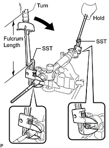
(b) Using SST, install the steering rack end sub-assembly (LH side).
SST: 09922-10010
Without SST – Torque: 84 Nm (852 kgf-cm, 62 ft-lbf)
With SST – Torque: 60 Nm (613 kgf-cm, 44 ft-lbf)
– Use SST 09922-10010 as shown in the illustration.
– Use a torque wrench with a fulcrum length of 345 mm (13.58 in.)
– This torque value is effective when SST is parallel to the torque wrench.
HINT: Using SST, hold the steering rack and install the steering rack end sub-assembly (LH side).
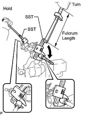
(c) Using SST, install the steering rack end sub-assembly (RH side).
SST: 09922-10010
Without SST – Torque: 84 Nm (852 kgf-cm, 62 ft-lbf)
With SST – Torque: 60 Nm (613 kgf-cm, 44 ft-lbf)
– Use SST 09922-10010 as shown in the illustration.
– Use a torque wrench with a fulcrum length of 345 mm (13.58 in.)
– This torque value is effective when SST is parallel to the torque wrench.
HINT: Using SST, hold the steering rack end sub-assembly (LH side) and install the steering rack end sub-assembly (RH side).
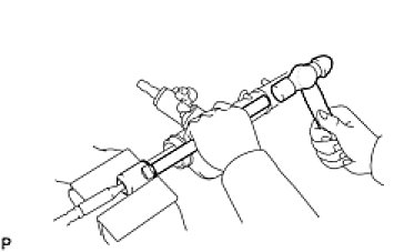
(d) Using a brass bar and a hammer, stake the 2 claw washers.
NOTE: Avoid any impact to the steering rack.
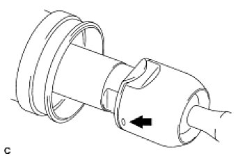
(e) Ensure that the holes of the rack ends are not clogged with grease.
HINT: If the hole is clogged, the pressure inside the boot will change after it is assembled and the steering wheel is turned.
18. INSTALL NO. 2 STEERING RACK BOOT
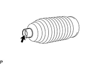
(a) Apply silicon grease to the inside of the small opening of the No. 2 steering rack boot.
(b) Install the No. 2 steering rack boot to the groove on the rack housing.
NOTE: Be careful not to damage or twist the No. 2 steering rack boot.
19. INSTALL NO. 1 STEERING RACK BOOT
HINT: Perform the same procedure as for the No. 2 steering rack boot.
20. INSTALL NO. 2 STEERING RACK BOOT CLAMP
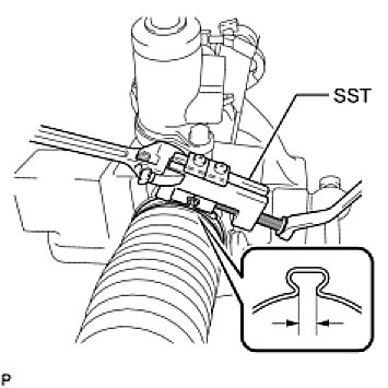
(a) Using SST, tighten the 2 No. 2 steering rack boot clamps as shown in the illustration.
SST: 09521-24010
Clearance:
2.0 mm (0.079 in.) or less
NOTE: Be careful not to damage the No. 2 steering rack boot.
21. INSTALL STEERING RACK BOOT CLIP
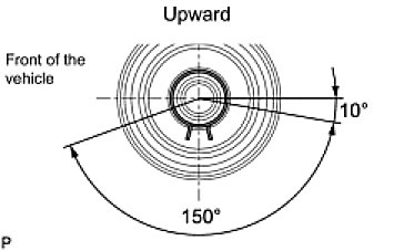
(a) Using pliers, install the 2 steering rack boot clips.
NOTE: Make sure that each clip claw is positioned within the area shown in the illustration.
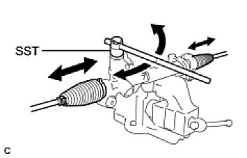
(b) Using SST, turn the pinion and check that the rack boots expand and contract smoothly.
SST: 09616-00011
22. INSTALL TIE ROD ASSEMBLY LH
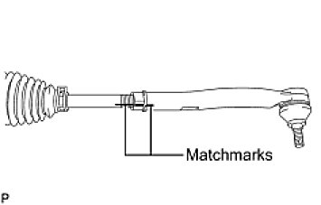
(a) Install the lock nut and the tie rod assembly LH to the steering rack end sub-assembly until the matchmarks are aligned.
Installation
INSTALLATION
1. INSTALL POWER STEERING RACK HOUSING HEAT INSULATOR (for 2GR-FE)
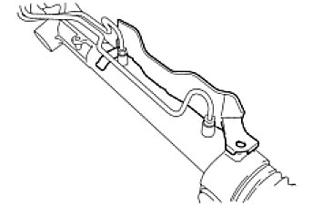
(a) Install the power steering rack housing heat insulator to the power steering link assembly.
2. INSTALL POWER STEERING LINK ASSEMBLY
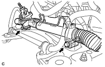
(a) Install the power steering link assembly with the 2 bolts and 2 nuts.
Torque: 70 Nm (714 kgf-cm, 52 ft-lbf)
3. CONNECT PRESSURE FEED TUBE ASSEMBLY
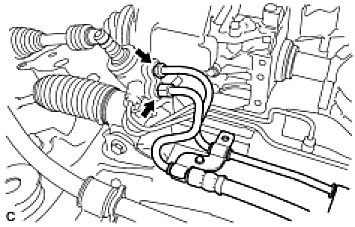
(a) Temporarily connect the pressure feed tube assembly to the power steering link assembly.
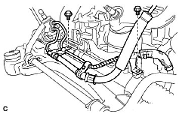
(b) Install the pressure feed tube assembly clamp with the 2 bolts.
Torque: 9.8 Nm (100 kgf-cm, 87 in-lbf)
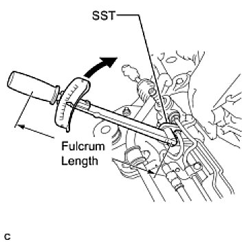
(c) Using SST, tighten the pressure feed tube assembly (pressure feed tube side).
SST: 09023-12701
Without SST – Torque: 25 Nm (250 kgf-cm, 18 ft-lbf)
With SST – Torque: 22 Nm (227 kgf-cm, 16 ft-lbf)
– Use a torque wrench with a fulcrum length of 300 mm (11.81 in.).
– This torque value is effective when SST is parallel to the torque wrench.
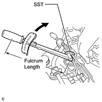
(d) Using SST, tighten the pressure feed tube assembly (return tube side).
SST: 09023-12701
Without SST – Torque: 25 Nm (250 kgf-cm, 18 ft-lbf)
With SST – Torque: 22 Nm (227 kgf-cm, 16 ft-lbf)
– Use a torque wrench with a fulcrum length of 300 mm (11.81 in.).
– This torque value is effective when SST is parallel to a torque wrench.
4. INSTALL ENGINE ASSEMBLY WITH TRANSAXLE
HINT: Refer to the instructions for installation of the engine assembly (Installation) for 2AZ-FE, (Installation) for 2GR-FE).
5. CONNECT TIE ROD ASSEMBLY LH
(a) Connect the tie rod assembly LH to the steering knuckle with the nut.
Torque: 49 Nm (500 kgf-cm, 36 ft-lbf)
(b) Install a new cotter pin.
NOTE: Further tighten the nut up to 60° if the holes for the cotter pin are not aligned.
6. CONNECT TIE ROD ASSEMBLY RH
HINT: Perform the same procedure on the other side.
7. CONNECT STEERING SLIDING YOKE
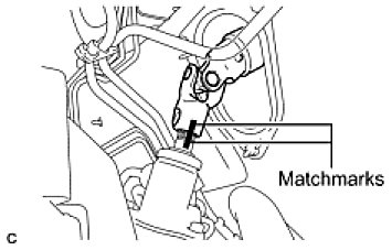
(a) Align the matchmarks on the steering sliding yoke and the steering link assembly.
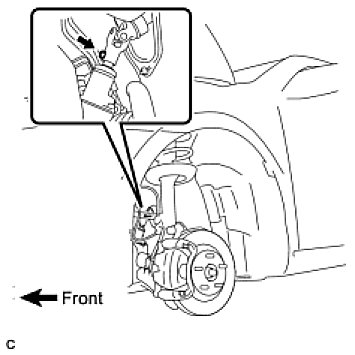
(b) Install the bolt.
Torque: 35 Nm (360 kgf-cm, 26 ft-lbf)
8. INSTALL FRONT WHEELS
Torque: 103 Nm (1,050 kgf-cm, 76 ft-lbf)
9. CONNECT CABLE TO NEGATIVE BATTERY TERMINAL
10. BLEED POWER STEERING FLUID (Service and Repair)
11. CHECK POWER STEERING FLUID LEVEL (Power Steering System)
12. CHECK FOR POWER STEERING FLUID LEAKAGE
13. CHECK FOR EXHAUST GAS LEAKS
14. PLACE FRONT WHEELS FACING STRAIGHT AHEAD
15. INSPECT AND ADJUST FRONT WHEEL ALIGNMENT
HINT: After adjusting toe-in, torque the lock nut.
23. INSTALL TIE ROD ASSEMBLY RH
HINT: Perform the same procedure as for the LH side.
24. INSTALL STEERING RIGHT TURN PRESSURE TUBE
(a) Coat 2 new O-rings with power steering fluid and install them to the steering right turn pressure tube.
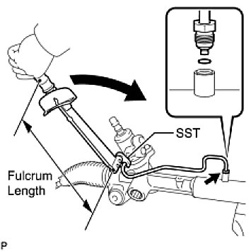
(b) Using SST, install the right turn pressure tube to the power steering link assembly.
SST: 09023-38201
Without SST – Torque: 13 Nm (128 kgf-cm, 9 ft-lbf)
With SST – Torque: 11 Nm (114 kgf-cm, 8 ft-lbf)
– Use a torque wrench with a fulcrum length of 250 mm (9.84 in.).
– This torque value is effective when SST is parallel to the torque wrench.
25. INSTALL STEERING LEFT TURN PRESSURE TUBE
(a) Coat 2 new O-rings with power steering fluid and install them to the steering left turn pressure tube.
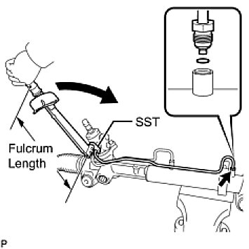
(b) Using SST, install the left turn pressure tube to the power steering link assembly.
SST: 09023-38201
Without SST – Torque: 13 Nm (128 kgf-cm, 9 ft-lbf)
With SST – Torque: 11 Nm (114 kgf-cm, 8 ft-lbf)
– Use a torque wrench with a fulcrum length of 250 mm (9.84 in.).
– This torque value is effective when SST is parallel to the torque wrench.